SIMPLE Time-Difference-Of-Arrival
RDF
Joe Leggio WB2HOL
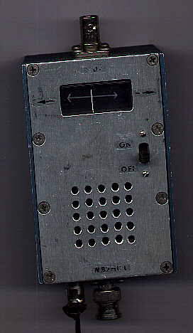
This T.D.O.A. RDF set is built into a die-cast Pomona
box. I built it in October, 1989. As you can see from the photo, it has
held up to lots of abuse as it gets knocked around in my RDF bag.
 How
it works
How
it works
Time Difference of Arrival RDF sets work by switching your
receiver between two antennas at a rapid rate. When both antennas are the
same distance from the transmitter, the RF phase received by both antennas
will be identical. If the two antennas are different distances from the
transmitter the RF will have a different phase at each antenna. If we switch
between the antennas 500 times a second, this phase change will be detected
by an FM receiver as a 500 Hz tone.
By turning the antennas for a null in the tone, your two antennas will
be perpendicular to the transmitter. Unfortunately, you can be facing the
transmitter or facing away from the transmitter and get a null in the tone.
By using a synchronous detector and processing the phase of the tone, it
is possible to drive a center scale meter to indicate which direction to
turn to face the transmitter.
If you have a null in the tone and turn slightly right, the meter should
point to the left and direct you to turn left to face the transmitter.
If instead, it points right as you turn right, you need to continue turning
right to face the transmitter; you were facing away from it originally.
(in other words, you need to turn 180 degrees around)
When you build this unit you must test it with *your specific receiver.*
The audio circuits in a receiver sometimes invert the audio phase and if
that is the case, the unit will read opposite of the true direction. If
this happens to you simply turn the antenna unit around or reverse the
connections to the meter.
If you look closely at the center of the antenna boom in the picture
below, you will see my markings on the antenna for one of my HTs. (I used
abbreviations, but it says "When using the Ten-Tec HT, this side of
the boom should be on the bottom and away from the transmitter")
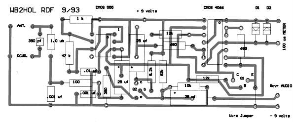
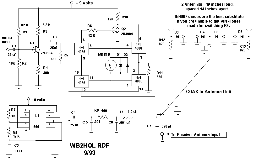
Circuit Description
This circuit is adapted from an idea which originally was
described in QST in an article for a Double Ducky direction finder. It
uses a CMOS 4066 as a synchronous detector. I used a CMOS 555 as a square
wave oscillator to drive both the antenna switching diodes and the synchronous
detector. I also added a stage of audio amplification to help drive a less
sensitive meter. This unit was originally designed to be mounted directly
on the antenna connector of my HT. This worked fine when I originally built
it. Today, I have a Yeasu FT50R. It is smaller than the TDOA unit and has
an SMA connector for the antenna. Somehow, I don't think it could support
the weight.
Audio is input via a cable connected to the earphone jack of the HT.
A small loudspeaker was mounted on the front of the T.D.O.A. RDF unit to
allow me to hear the FOX. The loudspeaker is not illustrated in the schematic
shown here. The T.D.O.A. RDF unit supplies voltage to the antenna unit
through the center conductor of the coax. The voltage alternately causes
the diodes connected to the antenna elements to conduct. As the diodes
conduct, RF is able to flow from one of the antenna elements to the receiver
The switching rate is set by the .01uf capacitor and the 47k resistor connected
to pin 2 of the 555. If you would like a different tone, try adjusting
the value of the 47k resistor.
This T.D.O.A. RDF unit uses a center scale meter to indicate which direction
to turn in order to face the transmitter. I used a surplus meter movement
in my TDOA RDF unit. It was not a center zero meter until I took it apart
and moved the mechanical zero adjust lever to make it so. I would guess
it was a 100 microamp meter movement originally. I think it was a signal
strength meter from an old FM broadcast band receiver. A more sensitive
meter would allow you to use less volume. I usually look for a 50 to 200
microamp zero center meter when building one of these units and can usually
find a bargain at one of the ham radio flea markets I attend. I never spend
more than five dollars for a surplus meter. The meter in this unit cost
me about a dollar. I would guess that even a 500 microamp meter could be
used. I would be less sensitive and require you to use a bit more volume.
The Printed Circuit Board
I used rub-on transfers (available from Radio Shack) to
lay out the PC board in this unit. It does not have the audio amplifier
stage which is present on the PC layout included on this web page. The
amplifier is needed when using less sensitive meter movements.
The PC board layout is shown here looking at the bottom of the board
as if you had X-ray eyes and could look through the board and see the parts
on top. There is one wire jumper. It is at the lower right side of the
PC board. The two transistors are 2N3904 or equivalent. The two diodes
across the meter movement are 1N914 or equivalent. The three 25uf capacitors
each have two different pads available for their leads. If you can obtain
parts small enough to fit the set of pads spaced closer together, use them.
There is nothing critical about the value of most of the parts. Anything
plus or minus 20 percent of the value indicated will work. (don't add 20%
to the 555 or the 4066. I doubt *that* would work!).
All of the resistors are 1/4 watt. The two diodes on the PC board are
connected "back-to-back" The PC layout illustrates how the diodes
should be mounted. The electrolytic caps should be rated for at least 10
volts. (assuming you are going to use a 9 volt battery). The 1.0 microhenry
coil used to couple the output from the 555 to the antenna was fashioned
by winding about 20 turns of number 22 AWG wire on a 3/16 inch drill bit.
It was then slid off of the drill and mounted on the PC board.
The Antenna Unit
Details of the antenna are shown below. The four antenna
elements should be fashioned out of stiff wire or metal rods. One club
member recycled a broken TV antenna and used 19 inch segments of its elements.
The schematic shows two antennas; you might be wondering why there are
four antenna elements. The extra two are connected to the coax shield at
the ends of the boom. These form a counterpoise for the two active elements.
The boom of the antenna must be less than 1/2 wavelength long. The longer the boom,
( up to 1/2 wavelenngth ) the more RF phase difference will be detected. I found that
spacing the antennas about 1/4 wavelength apart gave the best results. Further apart
resulted in more modulation but at the expense of portability. It also seemed a bit
less sensitive to multipath errors when I used the shorter boom. The antenna unit
pictured here has a 15 inch long boom.
The antenna must be constructed as symmetrical as possible. The lengths
of coax from the center BNC connector must be identical. A difference of
1/2 inch will cause an error of several degrees. If you use 1/2 wavelengths
of coax you only need one set of diodes where the coax connects to the
BNC connector at the center of the boom. If you find it easier to mount
a flange style SO-239 connector on the boom instead of a BNC, use it instead.
You will then need a cable with an PL-259 at one end and a BNC connector
at the other to connect the antenna to the RDF unit.
I have found that by mounting the antenna on a mast so it is up and
in the clear will result in the most accurate bearings.(It is then away
from reflections from your body and the ground) Whatever you do, make the
unit collapsible so it can be stored when not in use.
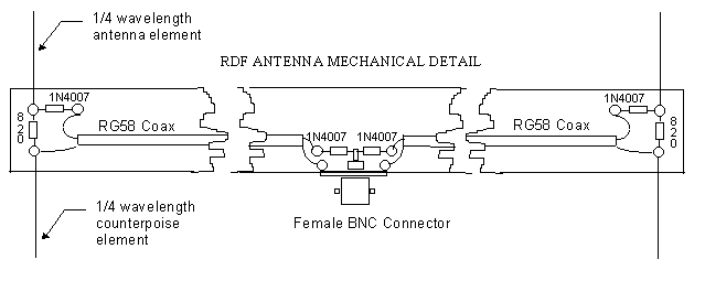
It is very important that the diodes on the antenna be connected as
shown on the schematic. Most diodes have a band which shows which end is
the cathode. The best diodes for use in the antenna are RF PIN diodes.
I used 1SS103 PIN diodes I purchased at a flea market. An equivalent
diode is the MPN 3404. In a pinch, you can substitute a 1N4007 power
diodes. They have a similar internal diode structure to the PIN diodes
and will work almost as well. The MPN 3404 is advertised at Dan's
small parts
 |
 |
| END OF RDF ANTENNA |
CENTER OF RDF ANTENNA |
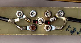
RDF Antenna Mechanical Details
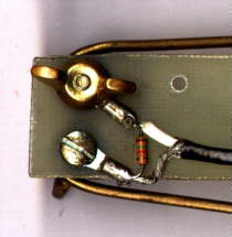
My antenna unit is designed to fold for storage. Wing nuts are used
to secure the elements in position. I used brass brazing rod for the antenna
elements on my latest hand-held unit. Earlier units used straightened out
coat hanger. On the unit pictured, I used 1/2 wavelength lengths of coax
between the center PIN diode and the antenna elements. This allowed me
to use only one pair of PIN diodes in the center. I coiled the coax and
secured it to the boom mid way between the center BNC connector and the
ends. RG-174 coax was used on the unit illustrated here to reduce weight.
The resistor in the picture is a 1.5k. The schematic below shows 820 ohms.
Remember, in this circuit, few part values are critical.
The antenna boom was made from a piece of scrap glass epoxy circuit
board material about 15 inches long and about 1 1/4 inch wide. I peeled
the copper from the board, mounted a BNC connector at the center, and used
small ring terminals secured by screws as tie points.The PIN diodes are
the small rectangular black parts with the red stripe at one end. The picture
shows them soldered to the back of a chassis mount BNC connector.
When you build your antenna make sure you mark one side as being the
side towards the transmitter. Also mark the TOP. The first time I used
this antenna, I started out walking away from the fox instead of towards
it because the antenna was being held upside down. (My antenna was visually
as well as physically symetrical) What amazed me was the number of other
hunters who followed me thinking I knew where I was going. For the second
fox hunt, I had marked the antenna. I won that event using this unit.
The Schematic
Back to RDF Projects page
Copyright 1997 - Joseph Leggio - all rights reserved.