Joe Leggio WB2HOL
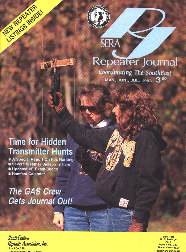
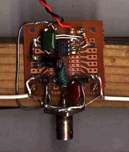
It uses a single 555 timer wired to produce a square wave output at about 500 Hz. 1N4007 power rectifier diodes were used in place of PIN diodes to switch between two dipole antennas at a 500 Hz rate. If you substitute another lower voltage power rectifier, it will work, just not as well. Of course, if you have RF PIN diodes, use them. (the 1N4007 is the only diode in the 1N400X series to contain a PIN diode structure) Power is supplied by a 9 volt battery.
I mounted the 555 oscillator circuit at the center of a 15 inch long piece of wood which acts as a boom to support two dipoles. The dimensions are not too critical. I used small brass screws as tie points at the ends of the boom and used wing-nuts to allow the dipole elements to fold against the boom when the unit was not in use.
I did not bother to add a power switch. I simply used a rubber band to secure the 9 volt battery to the boom and disconnect the battery from the circuit when I'm not using it.
How it works
Time Difference of Arrival RDF sets work by switching your
receiver between two antennas at a rapid rate. When both antennas are the
same distance from the transmitter, the RF phase received by both antennas
will be identical. If the two antennas are different distances from the
transmitter the RF will have a different phase at each antenna. If we switch
between the antennas 500 times a second, this phase change will be detected
by an FM receiver as a 500 Hz tone.
By turning the antennas for a null in the tone, your two antennas will be perpendicular to the transmitter. Unfortunately, you can be facing the transmitter or facing away from the transmitter and get a null in the tone. This circuit does not give you the ability to know if you are facing the transmitter or facing away from it. You must use triangulation to determine the correct direction. Although I have not tried it, you may also add a switched phasing line to your unit as shown here. This will result in a non-symmetrical receive pattern and allow an indication of which direction to travel.
The best method to tell the front from the back when using a TDOA RDF unit is by using a T.D.O.A. with a synchronous detector and processing the phase of the tone. It is then possible to drive a center scale meter to indicate which direction to turn to face the transmitter.
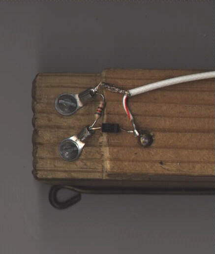
The Antenna Unit
Details of the antenna are shown below. The four antenna
elements should be fashioned out of stiff wire or metal rods. One club
member recycled a broken TV antenna and used 19 inch segments of its elements.
The schematic shows two antennas; you might be wondering why there are
four antenna elements. The extra two are connected to the coax shield at
the ends of the boom. These form a counterpoise for the two active elements.
I found that 15 inch lengths of wire "coat-hanger" worked well
as antenna elements for the unit pictured here. You can experiment to determine
the optimal length and distance between the dipole elements. (until you
run out of wire hangers, that is)
The boom of the antenna must be less than 1/2 wavelength long. The longer the boom, ( up to 1/2 wavelenngth ) the more RF phase difference will be detected. I found that spacing the antennas about 1/4 wavelength apart gave the best results. Further apart resulted in more modulation but at the expense of portability. It also seemed a bit less sensitive to multipath errors when I used the shorter boom. The unit pictured here has a 15 inch long boom.
The antenna must be constructed as symmetrical as possible. The lengths of coax from the center circuit board must be identical. A difference of 1/2 inch will cause an error of several degrees. Note that the layout of the antenna switching diodes on the experimenters PC board is symmetrical.
I have found that by mounting the antenna on a mast so it is up and in the clear will result in the most accurate bearings.(It is then away from reflections from your body and the ground) Whatever you do, make the unit collapsible so it can be stored when not in use. I used wing-nuts on the antenna elements to allow the unit to fold easily.
It is very important that the diodes on the antenna be connected as shown on the schematic. Most diodes have a band which shows which end is the cathode. The best diodes for use in the antenna are RF PIN diodes. I used 1SS103 PIN diodes I purchased at a flea market. An equivalent diode is the MPN 3404. In a pinch, you can substitute a 1N4007 power diodes. They have a similar internal diode structure to the PIN diodes and will work almost as well. The MPN 3404 is advertised at Dan's small parts
 |
 |
| END OF RDF ANTENNA | CENTER OF RDF ANTENNA |
The Schematic
Copyright 1998 - Joseph Leggio - all rights reserved.